One of the recurring challenges when documenting concrete setout drawings in Archicad is clearly communicating structural falls under wet areas. Bathrooms, laundries, balconies, and similar wet zones all require accurate slopes, correct levels, and compliant falls, both for construction and for coordination with engineers and builders.
While Graphisoft Archicad provides several native methods to model wet area falls, none of them fully address the combined needs of modelling accuracy, documentation clarity, and efficient workflow. This article explores the common approaches, their limitations, and a structured alternative that solves the problem in a more controlled and documentable way.
Native Archicad methods for modelling wet area falls
Archicad allows wet area falls to be modelled using tools that were originally designed for other purposes. The most commonly used are the Roof Tool and the Mesh or Terrain Tool.
Using the Roof Tool for wet area falls
A frequently used method is to apply the Roof Tool to create sloping planes within a wet area. Multiple roofs can be set up with slopes falling in different directions toward a drain or floor waste. By using Alt-click on the edge of a roof, it is possible to automatically trim one roof to another, allowing quite precise control over complex intersections.
This approach works reasonably well for simple roof geometry and can also be adapted for wet area modelling. However, as falls become more complex, the workflow quickly becomes time consuming. Managing several roof planes inside a small bathroom footprint is not intuitive, and changes late in the design process often require substantial rework. At some point, you start questioning whether the effort is justified for something that is not actually a roof.
The Multi-plane Roof tool is sometimes suggested as an alternative, but it has a critical limitation for wet areas. Falls can generally be directed upwards from the perimeter, not downwards toward a central or offset drain. This makes it unsuitable for most floor waste conditions found in real-world construction.
Using the Terrain or Mesh Tool
Another approach is to model the wet area using the Mesh Tool. This allows you to shape the surface to achieve falls toward a drain and visually represents the result quite clearly in 3D.
However, the mesh tool cannot be assigned a persistent thickness. If the wet area is intended to represent a floor finish or slab build-up, the mesh must be converted using “Create Roofs from Mesh” found under the Design Extras menu. While this works initially, it introduces another issue. If changes are required, the roofs must be deleted and recreated from the mesh again. Even if the original mesh is kept on a hidden layer, the recreated roofs lose their association with existing dimensions, labels, and annotations. This breaks documentation and creates unnecessary clean-up work.
Structural falls under slabs
Across all these native approaches, a larger issue remains unresolved. If you want the concrete structure itself to have a fall under the wet area, the typical workaround is to subtract roof geometry from a slab. While this may look correct in 3D, there is no clean way to document levels, slopes, or falls in a clear and repeatable manner. The information exists in the model, but it is effectively invisible to drawings, schedules, and consultants.
This is often where Archicad users feel they have hit a practical limit.
A single-object approach to wet area control
A different way of solving this problem is to treat the wet area as a single, intelligent object rather than a collection of adapted tools.
Using the Archibites wet area tool, the entire wet area can be controlled from one instance. Instead of juggling roofs, meshes, and slab subtractions, key parameters are defined directly.
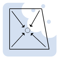
Perimeter levels and the floor waste or drain height can be set numerically. The floor waste can be positioned exactly where required, and different slope types of single, two, three, four or multiple falls can be set.
Levels and slope notation are automatically shown directly in 2D documentation, with options for rule-based controls to local standards. This means builders and engineers can clearly read the intent without interpreting complex geometry.
The tool also allows control over floor finishes. You can define whether the finish has a consistent thickness, whether a mortar bed is included, and whether the underlying structure is flat with a setdown or sloped to match the falls at a defined offset. This distinction is critical when coordinating structure versus finishes, yet it is difficult to manage using standard Archicad tools alone.
Using Model View Options, you can control whether the finish or the structural floor is displayed, with levels adjusted automatically to match the selected view. For pure 3D coordination, the object can be used to subtract from a slab, while the object itself remains responsible for all 2D documentation, including levels, slopes, and annotations.
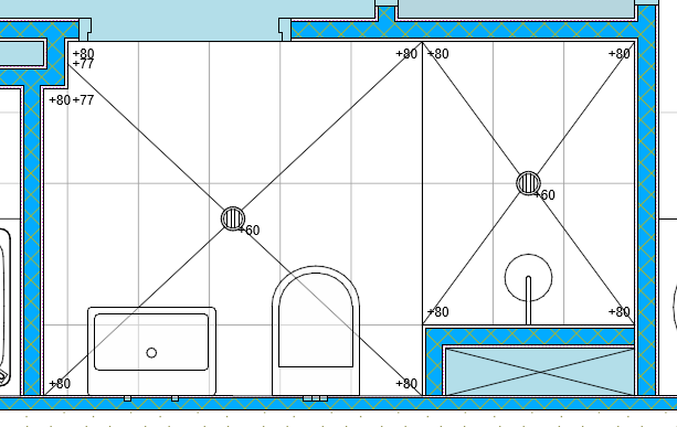
The image below has been set in model options to show structural falls under the finish level above. In this case allowing for 10mm Finishes and 50mm Mortar bed.

This approach keeps modelling, documentation, and coordination aligned, without relying on fragile geometry or manual redraws when changes occur.
A practical solution to a common Archicad problem
By using a purpose-built object designed specifically for wet areas, falls, and concrete setout, the process becomes more reliable and far easier to manage as drawings evolve.
You can see more about this approach here:
Archibites Wet Area Tool