While the Archibites Wet Area tool for ArchiCAD is designed to be highly intuitive, this article dives into the user interface settings to help you get the most out of its advanced features.
To kick things off, here are a few expert tips on how to build out your wet areas effectively.
1. Start with the Basics
The most common configuration you will create is the 4x linear slope to centre. We highly recommend starting with this type to familiarize yourself with the tool. A typical bathroom layout with a central floor waste uses this method, creating four distinct sloping planes that meet at the drain.
Crucially, these slopes provide a mathematically true representation of how the floor will actually be constructed. While we, as architects and designers, often simplify our drawings by just running ridge lines straight into the corners, doing so doesn’t always reflect real-world building practices and can be incredibly difficult to execute on-site.
2. Alternative Layouts & Feedback
If your design genuinely requires ridge lines to run perfectly to the corners, you can switch to the multi-slope type—though outside of unique design scenarios, it is rarely built this way. That said, we are always looking to expand our toolset, so please get in touch if there is a specific configuration you need that isn’t covered yet.
3. Managing Buildups & Documentation
For a standard buildup—like tiles on a mortar bed over a concrete slab with falls—simply select the appropriate construction type in the Construction tab. From there, you can either cut a void in your main slab or use a Solid Element Operation (SEO).
Through the Floor Pens & Fills tab, you have full control to display either the structural concrete falls or the finished surface falls. Similarly, if you are utilizing a pedestal construction type, you can choose whether to display the underlying concrete gradients or the flat, finished surface of the tiles.
4. Compliance & View Control
Compliance Automation: Turn on the built-in rules to instantly highlight non-compliant gradients. You can quickly adjust your slopes in real time until the color highlights disappear, ensuring peace of mind for your documentation.
Model View Options (MVO): Take full advantage of native MVO settings to dynamically control how your wet areas display across different drawing types and documentation stages in your project.
UI Breakdown: The Construction Tab
The Construction tab houses the core parameters for your layouts
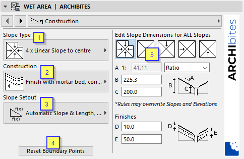
- Slope type (1). Choose from single all the way up to 4-way and multiple slope construction types. The 1,2,3,4-way slopes have a linear plane slope set relative to the drain point. The multi-slope sets the plane slope perpendicular each boundary edge, for unique circumstances. It is recommended you use the linear slope type as it fits most cases.
- Construction (2). Set here the layers of construction, be it finishes, mortar and/or concrete.
- Slope Setout (3). Set here how the slope is controlled. In most cases ‘Automatic Slope & Length, Set height’ will be the most common setting as it enables you to define a height at the boundary and the slope fall and slope length (from lowest point to heightest point) will automatically adjust to the nearest boundary. Rules can be used to further adjust this as explained later. Other options can be used for fine tuning more complex layouts ‘Automatic slope, set height and length’ allows a custom length of the slope to be set for each plane whilst the slope/fall is automatically calculated. ‘Automatic height, set slope and length’ allows the slope/fall and the length of the slope to be set manually whilst the height is automatically calculated.
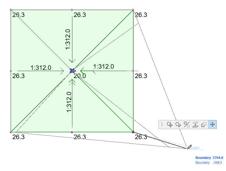
- Reset Boundary Points (4). If you want to reuse an existing placement of the object which has complex boundaries you can click here to reset its shape to a simple square shape to start from.
- Edit Slope (5). For a 4-way slope you can choose to edit all slopes together or individual slopes.
- A. Set the slope. Choose from Ratio, Percentage, Angle or ‘per Foot’.
- B. Set height of slope at end. This is the height at the end of the slope line on plan.
- C. Set height of slope at drain. This is the height of the drain, which is the start of the slope line on plan.
- D. Finish Thickness
- E. Mortar Thickness
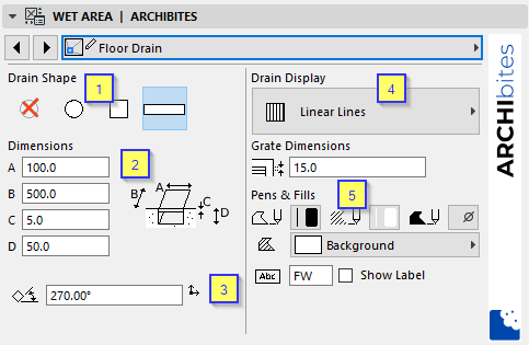
The Floor Drain tab.
- Drain Shape (1)
- Drain Dimensions (2)
- Drain Rotation (3). Or rotate on plan, slopes update automatically.
- Drain Display (4). Set the style of drain from diagrammitic for concrete, simple and complex shapes with grate lines. This can also be controlled via model view options.
- Pens & Fills (5).
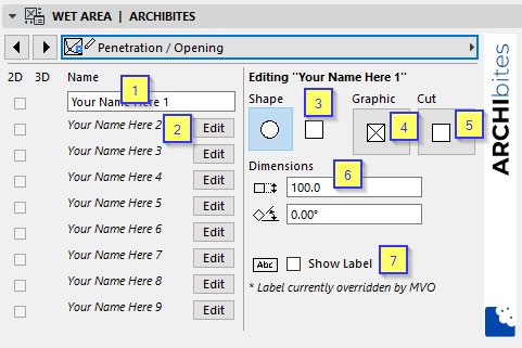
In additional the drain, penetrations for other services can be added.
- Name (1). Add a name for a pentration here and also use tick boxes to turn on or off in 2s and/or 3d. Visibility can also be set in model view options.
- Edit (2). Select which penetration to edit. The selected penetration settings will be shown on the right.
- Shape (3)
- Graphic (4). Display setting in floor plan.
- Cut (5). Which layers the penetration cuts through. For pedestal type construction you may only want to cut through the concrete.
- Penetration dimensions (6)
- Label (7). Note model view options will override this setting.
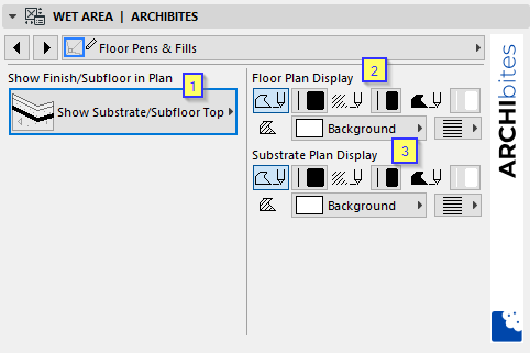
Set the Floor Graphics, Pens and Fills
- Plan view (1). Set here to show the Finish, or Substrate Top, or Substrate. Useful to show just the concrete falls under the finishes in concrete setout plans with corresponding levels or the finish for general plans. Also set in model view options.
- Finish view (2). When set to finish, pens and fills
- Substrate view (3). When set to substrate, pens and fills
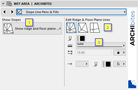
Use the Slope lines tab and the Slope Line Text to
- Line Visibility (1). Show plane slopes and/or ridge slopes. Or set by Model view
- Edit Line (2). Edit plan slope lines or ridge slopes, or both. The settings for the selected slope will display below.
- Graphics (3). Select Pens, linetypes, dimensions and arrowheads. The length of the slope can also be set here to be either full length or to a set length. Note when slope plane falls have a short length and in the construction tab slopes are set to a custom length, some small dots will be shown as guides for stretching on plan, the pen of these can be set to be the same as the floor if desired.
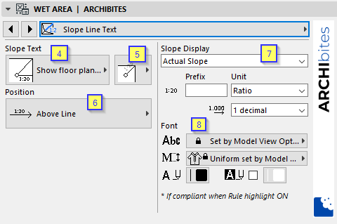
- Text Visibility (4). Show plane slopes and/or ridge slopes. Or set by Model view
- Hide Text (5). If text is longer than line then can hide text.
- Position (6). Above or below line.
- Slope type (7). Show actual slope or display the minimum or maximum set rule. Set Prefix, type of slope and decimal/fractions.
- Font (8).
Elevation Text Controls
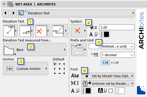
- Visibility (1). Show Elevation text on perimeter, slope high point, drain, flat finish/substrate. Also set to control by model view options.
- Measure text from (2). Select base point to calculate elevations from. Also set to control by model view options.
- Anchor (3). Use custom anchor, automatic placement or custom placement options for desired control.
- Symbol (4)
- Prefex and Unit (5)
- Font (6)
Use the Label Settings tab for label graphic settings for drain and penetrations
Use the 3d Floor Settings tab for all cut pens, fills and elevation surfaces and building materials
Use the 3d Drain tab for all cut pens, fills and elevation surfaces and building materials. Option can also be set to show or hide the drain coverplate.
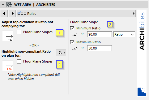
Rules allow automatic adjustment of heights or highlights where not meeting your local standards.
- Automatic Adjust Height (1). Where slopes do not meet your set rules (3) the height of the top of the slope will be adjusted automatically.
- Highlight non-compliance (2). Where slopes do not meet your set rules (3) they will be highlighted on plan. Use this to manually adjust slope lengths and height until you achieve compliance.
- Define rules (3). Set a minimum slope accordingly to your local requirement, and/or set a maximum slope. Any slopes outside of these constraints will be acted on depending on set (1) and (2).